
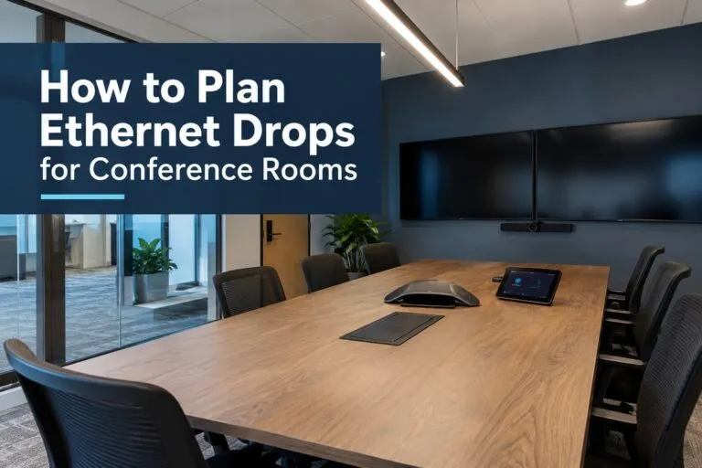
How to plan Ethernet drops for conference rooms requires more than deciding where to place a few network jacks. Conference rooms now support video conferencing systems, room controllers, wireless access points, displays, VoIP phones, scheduling panels, presentation equipment, and other network-connected devices. A well-planned conference room network installation gives IT teams enough wired connectivity for current equipment while leaving practical capacity for upgrades, troubleshooting, and equipment changes.
For IT managers, facilities leaders, and corporate technology teams, Ethernet drop planning should happen alongside room layout, audiovisual design, furniture placement, electrical planning, and structured cabling decisions. Once walls are closed, tables are installed, and displays are mounted, adding network cabling can become significantly more disruptive and expensive.
Start With the Conference Room Technology Plan
Before determining Ethernet drop locations, document every device that may require a wired network connection. Do not base the cabling design only on laptops or the conference room table.
Modern meeting rooms can have network equipment distributed across walls, ceilings, tables, equipment cabinets, and entrances. Knowing where these devices will physically reside helps determine the correct cable pathways and termination points.
Common devices that may require Ethernet connectivity include:
- Video conferencing codecs and appliances
- Microsoft Teams Rooms or Zoom Rooms equipment
- Conference room PCs
- VoIP conference phones
- Touchscreen room controllers
- Scheduling and room-booking panels
- Wireless access points
- Network-connected displays
- Digital signage players
- AV-over-IP equipment
- Cameras
- Microphone and audio processing equipment
- Building automation or occupancy devices
- Table connectivity systems
- Remote management equipment
Some devices may ultimately connect over Wi-Fi, but critical conference room technology often benefits from wired Ethernet because it provides predictable connectivity and reduces dependence on the room’s wireless environment.
Plan Ethernet Drops Around Device Locations
A conference room should not be treated as one cabling location. Ethernet drops need to be positioned around the equipment they serve.
A network jack on one wall may technically provide connectivity to the room, but it does little for a ceiling-mounted wireless access point, a scheduling panel near the door, or equipment installed behind a display.
Conference Room Table
The conference table is one of the most important locations to consider. Depending on the room design, table connectivity may support conferencing hardware, phones, control panels, presentation interfaces, or temporary wired connections.
Floor boxes are frequently used in larger conference rooms where cables need to reach a central table without being exposed across walking paths. Another option is routing cabling through furniture systems when the conference table is designed with integrated cable management.
When planning table drops, consider installing more ports than the initial equipment requires. If the current design needs two network connections, providing additional capacity can make future equipment changes considerably easier.
Display and Video Conferencing Wall
The primary display wall often contains the highest concentration of technology in the conference room.
Displays, video conferencing appliances, mini PCs, AV-over-IP devices, control processors, cameras, and related hardware may all be located behind or near the display.
Rather than relying on a single Ethernet jack, determine the total number of network-connected devices expected at this location and provide additional capacity where practical.
The cabling should also terminate where technicians can access it after the displays and mounting hardware are installed.
Conference Room Entrance
Room scheduling panels are commonly installed outside or immediately inside the conference room entrance.
If the scheduling panel uses Power over Ethernet, an Ethernet drop at the entrance can provide both network connectivity and power through one cable. The exact mounting position should be coordinated with the room-booking hardware before cabling installation begins.
This is an easy location to overlook because it is physically separated from the primary conference room equipment.
Ceiling Locations
Ceiling-mounted devices require their own planning.
A wireless access point may need a dedicated Ethernet cable above the ceiling, while some conferencing systems use ceiling microphones, cameras, sensors, or other IP-connected equipment.
Coordinate ceiling Ethernet drops with lighting, HVAC equipment, speakers, fire protection systems, and architectural features so network devices can be installed in appropriate locations.
Determine How Many Ethernet Drops the Room Needs
There is no universal number of Ethernet drops that works for every conference room. The correct quantity depends on room size, conferencing technology, AV design, user requirements, and anticipated expansion.
A useful approach is to create a device count for each physical area of the room rather than assigning an arbitrary number of drops.
For example, the plan could include:
- Multiple Ethernet drops behind the primary display
- Multiple drops at the conference table or floor box
- One dedicated drop for the wireless access point
- One drop for the room scheduling panel
- Dedicated drops for additional cameras or AV equipment
- Spare Ethernet ports for future devices
Spare capacity is especially valuable in conference rooms because collaboration technology changes frequently. Adding one or two additional cable runs during the initial structured cabling installation is generally much easier than returning later to run cable through finished walls and ceilings.
Account for Power over Ethernet
Power over Ethernet, or PoE, can simplify conference room technology installations by delivering network connectivity and electrical power through the same Ethernet cable.
Potential PoE devices in conference rooms include wireless access points, VoIP phones, room scheduling displays, cameras, control panels, sensors, and certain AV devices.
Planning Ethernet drops for PoE equipment requires coordination with the network switching infrastructure. It is not enough for the cable to support the connection. The switch must also provide the appropriate PoE standard and sufficient available power budget.
IT teams should verify:
- Which conference room devices require PoE
- The PoE standard required by each device
- Switch compatibility
- Available PoE power budget
- Cable category and installation requirements
- Whether redundant or backup power considerations apply
This becomes particularly important during multi-room or multi-site conference room deployments where dozens or hundreds of PoE devices may be added to the network.
Choose the Appropriate Ethernet Cabling
Cable selection should account for bandwidth requirements, installation environment, expected service life, and organizational cabling standards.
Cat6 is widely used for enterprise structured cabling installations and can support many conference room applications. Cat6A may be appropriate where organizations want additional performance headroom, improved support for higher-speed networking over longer distances, or a cabling platform designed for a longer technology lifecycle.
The choice should be made according to the organization’s network architecture rather than simply selecting the highest category available.
IT and facilities teams should also consider plenum requirements, pathway capacity, bend radius, cable management, local building codes, and applicable structured cabling standards.
Coordinate Ethernet Drops With AV Design
Network cabling and audiovisual systems are increasingly interconnected. Planning them independently can create avoidable installation problems.
An AV contractor may specify equipment behind a display, underneath the table, inside a credenza, or above the ceiling. The structured cabling team needs those locations before cable pathways and terminations are finalized.
Coordination should cover the number of Ethernet connections, exact termination locations, mounting heights, equipment rack locations, floor boxes, conduit, cable pathways, and access requirements.
Avoid Ports That Become Inaccessible
A network jack is not particularly useful if technicians cannot reach it.
Wall plates installed directly behind fixed displays, furniture, millwork, or mounting brackets can become difficult to access after installation. The network and AV plans should be reviewed together so ports remain serviceable.
For display walls, verify the mounting bracket dimensions before finalizing Ethernet outlet placement. A few inches can determine whether a port is accessible or blocked by mounting hardware.
Plan the Path Back to the Telecommunications Room
Every Ethernet drop eventually needs to connect to network infrastructure.
Conference room planning therefore needs to extend beyond the room itself. Determine which telecommunications room, intermediate distribution frame, or network closet will serve the conference room and confirm that the complete cable path is viable.
Check for:
- Available patch panel capacity
- Available network switch ports
- PoE-capable switch ports where required
- Cable pathway capacity
- Appropriate cable distance
- Rack capacity
- Patch cord requirements
- Cable management
- Labeling standards
This becomes particularly important when renovating existing offices. A conference room may have space for new wall plates while the serving network closet has little remaining rack, patch panel, or switch capacity.
Build Spare Capacity Into the Cabling Plan
Conference rooms tend to accumulate technology.
A room initially designed with one display and a basic conferencing appliance may later receive dual displays, a different room system, occupancy sensors, upgraded cameras, AV-over-IP equipment, or additional control hardware.
Running spare Ethernet cables to strategic locations can reduce the amount of construction required when these changes happen.
Good locations for spare cabling may include the display wall, conference table, ceiling, AV cabinet, and other technology-heavy areas.
Spare cables should be properly terminated or secured, labeled, documented, and included in the as-built cabling records. An unidentified cable hidden above a ceiling provides little operational value.
Label Every Conference Room Ethernet Drop
Clear labeling is essential for conference room network management.
Each Ethernet jack should correspond to a clearly identified patch panel port in the telecommunications room. Labels should follow the organization’s structured cabling naming convention and remain consistent across rooms, floors, and buildings.
For example, documentation should allow a technician to quickly determine which switch or patch panel connection serves a specific conference room port.
Accurate labeling is particularly valuable for remote hands and IT field services. A technician dispatched to troubleshoot a conference room can locate the correct connection without tracing cables or repeatedly contacting the network team for clarification.
Test and Certify the Installed Cabling
Installing the cable is only part of the job. Ethernet drops should be tested before the conference room is considered ready for technology installation.
Structured cabling certification can identify problems involving termination quality, cable length, wire mapping, performance, or damaged cable.
Testing should occur before the room is fully commissioned whenever possible. Discovering a failed Ethernet run after furniture, displays, AV equipment, and architectural finishes are installed can make remediation much more difficult.
Test results should also be retained with project documentation, especially for enterprise network cabling projects involving multiple conference rooms or locations.
Coordinate Conference Room Cabling Across Multiple Sites
Ethernet drop planning becomes more complex during multi-site IT rollouts.
If an organization is deploying standardized conference rooms across dozens of offices, inconsistent cabling can create unnecessary variation in installation and support. One location may have four ports behind a display while another has two. Scheduling panels may be cabled differently, or wireless access points may terminate in inconsistent locations.
A standardized conference room cabling specification can define:
- Required Ethernet drop quantities by room type
- Standard port locations
- Cable category
- Labeling conventions
- Patch panel requirements
- Testing and certification requirements
- PoE requirements
- Spare cabling requirements
- Documentation and closeout standards
Standardization makes conference room deployments easier to repeat and simplifies ongoing IT support because technicians encounter similar network layouts from site to site.
Include Ethernet Drops in the Construction Schedule
Ethernet cabling needs to be coordinated with the broader construction or renovation schedule.
Cabling pathways, conduit, floor boxes, wall penetrations, and above-ceiling access may need to be completed at specific stages of construction. Waiting until the conference room technology is ready to install can be too late.
IT, facilities, general contractors, AV teams, electricians, and structured cabling contractors should confirm responsibilities before work begins.
A typical sequence may involve pathway preparation, cable installation, termination, labeling, certification, network patching, equipment installation, and final connectivity testing.
Clear sequencing helps prevent situations where technicians arrive to install conference room equipment but the required Ethernet drops are missing, inaccessible, or not connected to active switch ports.
Document the Finished Conference Room Network
The final network configuration should match the documentation handed to IT operations.
As-built records should identify Ethernet drop locations, cable IDs, patch panel ports, switch connections where applicable, room numbers, and relevant equipment assignments.
Photos can also be useful, particularly for connections located behind displays, inside floor boxes, above ceilings, or within AV cabinets.
Good documentation makes subsequent moves, adds, changes, troubleshooting, and conference room refresh projects easier to manage.
Planning Ethernet drops for conference rooms works best when IT infrastructure, AV requirements, furniture layouts, electrical systems, and physical construction are coordinated before installation begins. The objective is not simply to provide enough network ports for today’s equipment, but to create an organized and serviceable conference room network that can support technology changes without unnecessary recabling.
For organizations completing conference room upgrades, office renovations, structured cabling projects, or multi-site IT deployments, establishing a repeatable Ethernet drop standard can improve installation consistency and simplify long-term support. A carefully planned cabling layout gives technicians the connectivity they need at the table, display wall, ceiling, entrance, and other technology locations while keeping the network infrastructure documented, accessible, and ready for the next equipment refresh.